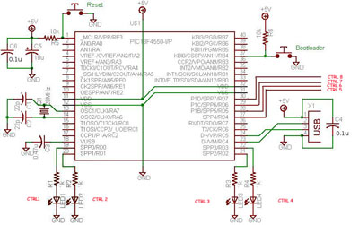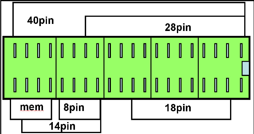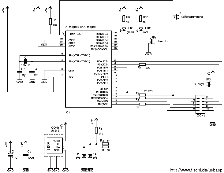

Connect it through a serial cable to a computer Ģ. These are the steps to use the programmer:ġ. Then we used the UV exposure method to transfer the circuit to the board and for last, we corroded the PCB with iron perchlorate.Īnd the programmer is ready to use! Here’s how it looks: Then we started making the PCB, first we printed the layout on an acetate sheet. Using the KiCad software, a PCB layout was designed: Therefore, an external voltage source must be connected to the 2-pin connector. The pin no.8 from the DB9 connector is connected to the PGD pin (40) in the PIC. According to the schematic, these resistors are connected to the following pins of the PIC: MCLR (1), PGC (39) and PGD (40).

This is an example of a very simple PIC programmer:Īs shown above, there are only three 4,7k resistors connected between the DB9 connector and the PIC.
#USB PIC PROGRAMMER SCHEMATIC FREE#
PICs are very popular as they are relatively cheap and because of their characteristics, for example their low power consumption, internal oscillator and free development tools. There are various families of micro-controllers, one of those is the Microchip’s PIC (Peripheral Interface Controller). Micro-controllers play a very important role in electronics, as they are able to perform tasks in automation, control, image processing, among others.

While we’re still working on the next workshops, here’s a very simple and useful mini project, a low cost 40 pins PIC programmer using the serial port.


 0 kommentar(er)
